How to Install a Passive WDM System the Right Way
Posted by Larry Legg on Jan 13, 2020
Congratulations! You have learned all about the benefits of fiber-conserving of a passive system, as well as the cost and operational advantages over an active system. Your new passive filters and transceivers have arrived and are ready to deploy, so what is the next step? This short guide will walk you through the best practices for deployment so you can minimize the risk of mistakes and quick deployment.
Before We Start…
This guide can be applied to any Champion ONE passive filters (CWDM or DWDM) that have different channel counts. However, for this guide, we will use our 8 Channel CWDM Mux/Demux with a simple point-to-point configuration between two locations as an example.
Before you start plugging in, make sure you have transceivers for all required channels at each location. Also, confirm that all your fiber is in optimal condition to avoid future problems. Specifically:
- Use an OTDR to verify the continuity of the Outside Plant (OSP) fiber you will use to connect your locations
- Always clean and scope your fiber jumpers before connecting
Start Connecting
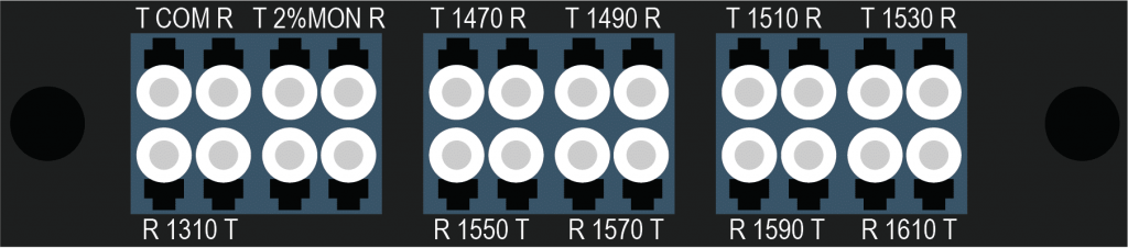
Our ZS series of passives simplifies the language of wavelength division multiplexing. Instead of having to remember which signal goes to “mux” or “demux,” simply connect the Transmit (Tx) on your transceiver to the “Receive” (R) on your mux/demux — or vice versa.
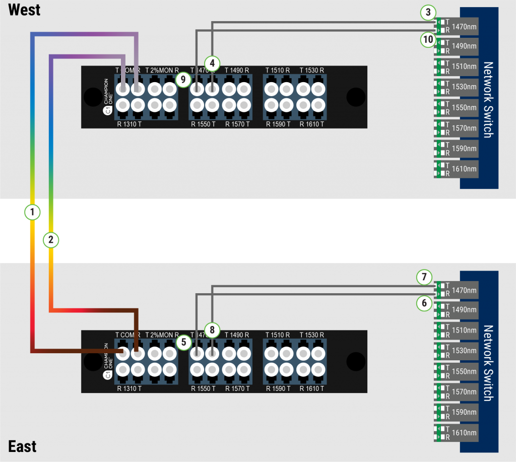
The exact sequence of these connections is depicted in the diagram below. Just follow these two steps:
- On the COM ports on your units, connect R at the West side and T at the East side
- Connect T West to R East
Congratulations! Your locations are now linked. Now it is time to light some channels.
Lighting a Channel
NOTE: Follow the steps below for each channel. We will start with 1470nm, as depicted above:
3. Connect a clean, scoped fiber jumper to the West Transceiver Tx. Then verify the output level with a channel-specific power meter.
4. Connect the opposite end of your fiber jumper to the West 1470 R on your mux/demux.
5. Connect a clean, scoped fiber jumper to the East 1470 T on your mux/demux. Then verify the output level with a channel-specific power meter.
6. Connect the opposite end of your fiber jumper to the East Transceiver Rx. Then verify your newly-established one-way connectivity per your equipment manufacturer’s instructions.
7. Connect a clean, scoped fiber jumper to the East Transceiver Tx. Then verify the output level with a channel-specific power meter.
8. Connect the opposite end of your fiber jumper to the East 1470 R on your mux/demux.
9. Connect a clean, scoped fiber to West 1470 T on your mux/demux. Then verify the output level with a channel-specific power meter.
10. Connect the opposite end of your fiber jumper to West Transceiver Rx.
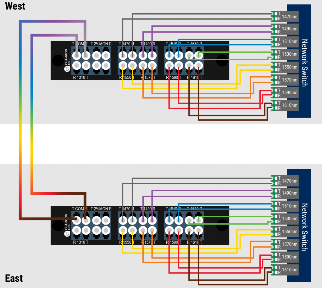
You now have full connectivity! Confirm your channel link is showing as “Up-Up” and that no “LOS” alarms are showing on any ports.
You are ready to move on to your next channel. To do so, simply repeat steps 3 through 10 in the same order.
Want to learn more about passive architectures? Discover the cascade and Hub-and-Spoke designs on our Solutions page.