A Guide to Filters and Splitters
Posted by Larry Legg on Mar 24, 2023
Choosing the right optical filter is like choosing the best sunglasses for your eyes. Too dark, and it may be too difficult to see; too light, and they are less effective at blocking the sun. With levels of UV (ultraviolet) light protection, and polarized vs. non-polarized lens, each will affect your vision differently, letting through a certain amount or particular types of light.
Optical filters work similarly, but instead of filtering sunshine, they filter laser light. Very specific spectrums of that laser. These lasers originate from integrated onboard optics or pluggable transceivers.
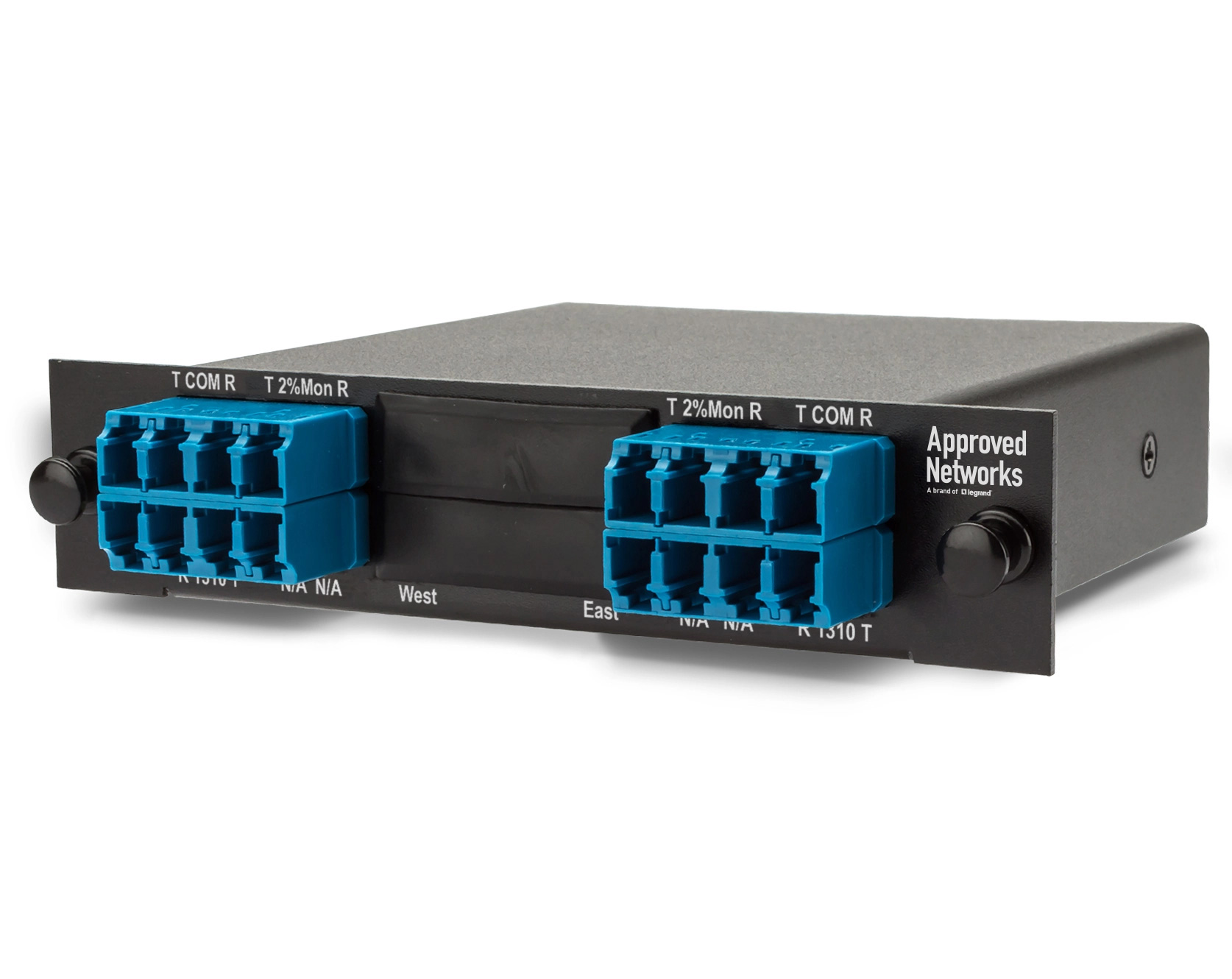
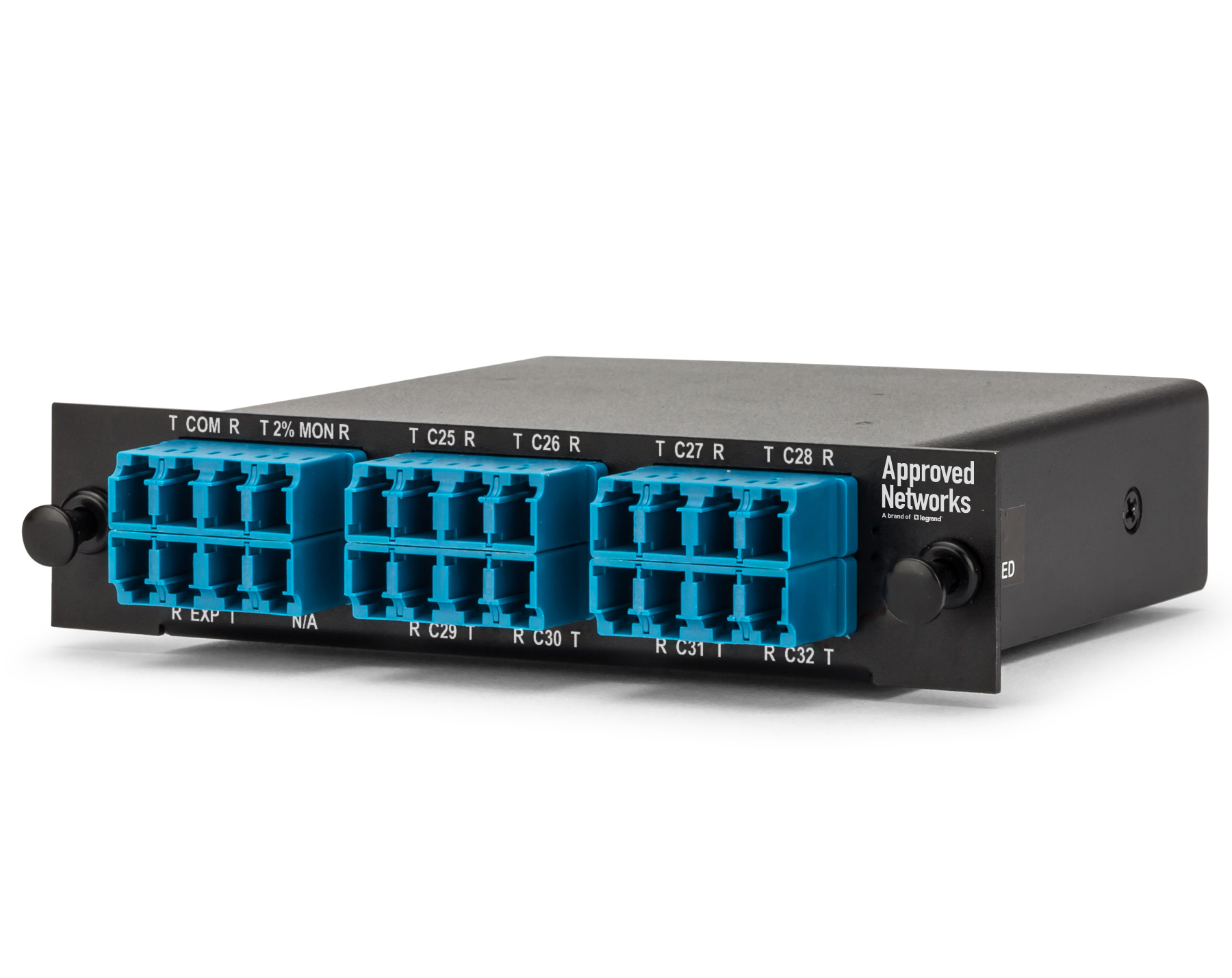
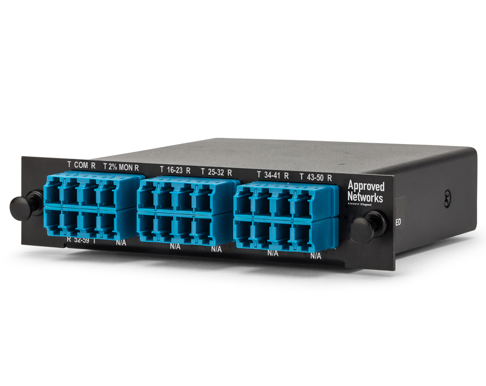
Optical filters play a key role in fiber optics, and as usual, they are offered in a plethora of acronyms: DWDM, CWDM, FWDM, MUX / DEMUX, OADM.
For example, the wavelength selectivity needed for an Optical Add-Drop Module (OADM) fine tunes the light by selectively adding and dropping optical channels. And since OADM can be for low-loss/low-cost passive devices, it doesn’t require any power, making it scalable, reliable and cost-effective.
The filters for WDM (Wavelength-Division Multiplexing) combine multiple signals for multiplexing and demultiplexing with each laser modulated for a pair of signals. There are also CWDM (Course Wavelength-Division Multiplexing) and DWDM (Dense Wavelength-Division Multiplexing) to throw in the mix.
You can see how the type of filter or filters you need depends on the wavelengths you’re working with. The transceiver wavelengths must match the filter ports to pass through the filter.
Since the CWDM filter’s purpose is to separate one signal from a group of signals, the wavelengths of light corresponding to the CWDM channel filter is allowed to pass while all others are reflected.
A single DWDM channel uses a filter to transmit and reflect other DWDM channels. In high-speed optical networks, DWDM filters have multiplex and de-multiplex wavelength signals that are evenly spaced from 1525 to 1640 nm.
It is important to note we are focusing on the C-Band (or conventional band) in the 1530-1565 nm wavelength range — not the L-Band (long 1565–1625 nm) or S-Band (short 1460–1530 nm). However, there are significant developments in the O-Band DWDM (1295-1312 nm), sometimes referred to as LAN-DWDM, look for future announcement from us.
Filters pass the wavelengths of light that do not need to be dropped, and reflect through the wavelength(s) that are needed.
The three most common filter types for C-Band DWDM are: Thin Film filters (TFF), Flat-Top and Gaussian filters. They each have their own specific use cases depending on a myriad of variables including transceiver modulation, channel count, filter configuration and your system topology. Contact us to set up a call to see what fits your network best.
Yes, that’s a lot of information, which means there is a lot to consider when choosing the proper filter for your fiber optics.
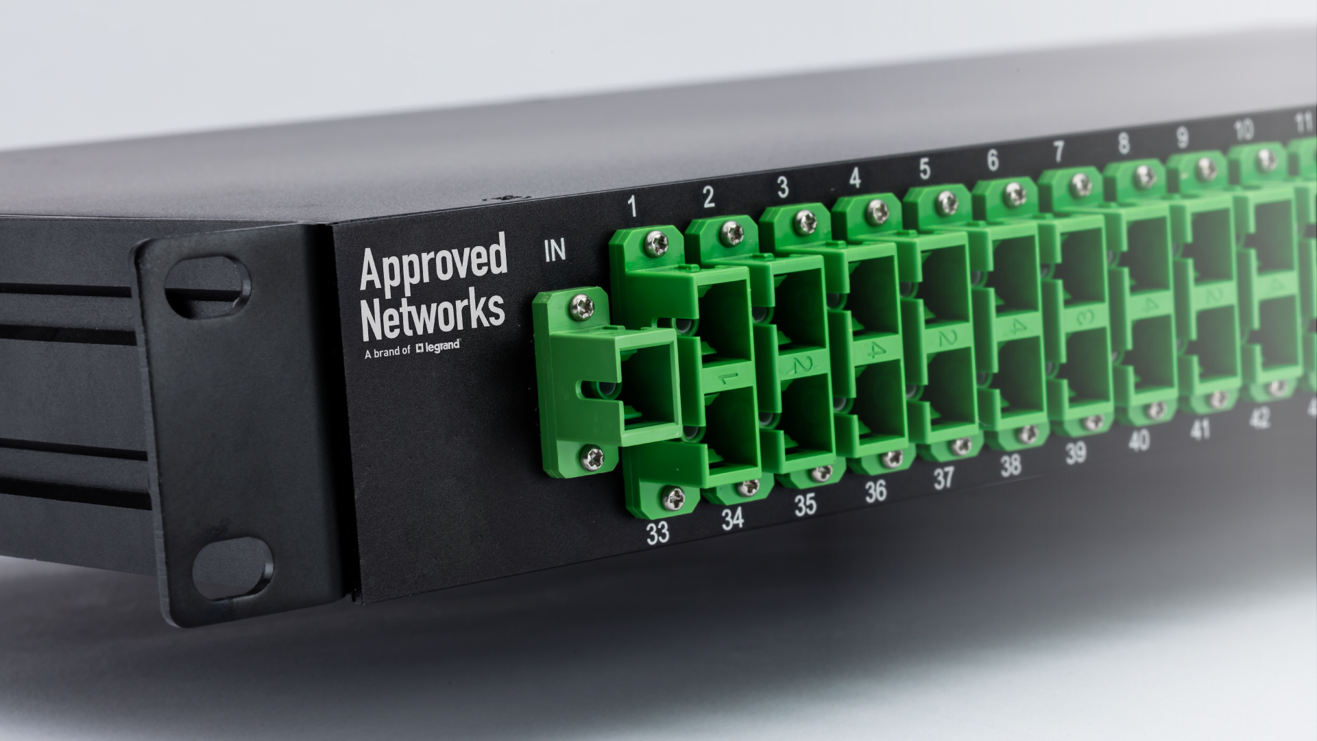
A fiber optic splitter, on the other hand, takes the signal and — BOOM! — splits it. It can also be called an optical splitter or optical TAP.
Why would you want to split the signal of a fiber optic cable? To send the light into multiple directions, basically distributing the beam for multiple inputs and outputs. They’ve been important in passive optical networks for, as an example, a single PON interface to be shared among many subscribers.
In general, optical splitters have been widely used in PON networks. FTTH is one of the common application scenarios, and typical architectures are Optical Line Terminal (OLT) located in the central office (or head-end), to the Optical Network Unit (ONU) situated at the user end.
Of course, if the signal is split, the optical power output of the wavelengths is reduced by the number of splits. If you broadcast with 1000 Mbps, and split it 4 ways, you’ll be able to share 1000 Mbps at the end of each split. This is commonly referred to as a broadcast network.
There are “1xN” splitters — where the “N” is the number of splits, like 1x2, or 1x8. This is the split-ratio. There are also 2xN splitters. This allows two inputs into the split network, such as GPON and XGS-PON into the same split network.
So, it gets more complicated if you have, say, 2 signals going in and then split it to 64 endpoints. Because networks have greatly increased to serve more subscribers, this kind of scenario is not unusual. With the rapid growth of FTTx (FTTB, FTTH, etc.) there is a requirement for a higher split-ratio.
This, like everything in the networking world, has both advantages and disadvantages. Fiber optic splitters with higher split-ratios can share the optics, electronics, fiber and new install costs. Also, larger splits allow more flexibility and fiber management at the head end is simpler.
However, higher split-ratio splitters increases the endpoints sharing the same bandwidth from the OLT. PON Networks with longer distances and high-loss fiber cannot stand high split-ratios due to necessary optical power budgets.

Figure 1
The other disadvantage of high split-ratio is when you split a network with additional OLTs such as splitting a 1x64 into (two) 1x32’s, then you have to move an extreme number of fibers to accomplish this, impacting customers. So be mindful how many times you split the bandwidth from an OLT. And if you like cream in your coffee, or your peanut butter with jelly, we have coexistence modules that add both filters and splitters in the same device. This allows you to run DWDM services over the top of PON services on the same single fiber.

Figure 2
 Figure 3 — Drop and Continue WDM
While filters and splitters do different things, they can be used together to give you the results you want. But as you’ve seen, there are a lot of options and variations to choose from, so you need to determine what is required for your network beforehand so it can work at its most optimal.
Feel free to contact an account manager at Approved Networks to connect you with one of our solution experts for any of your fiber optic requirements.
