How to Get Higher Efficiency During Deployment
Posted by Robert Isaac on May 2, 2022
In previous articles, we discussed how using passive Dense Wave Division Multiplexing (DWDM) can help Data Center Engineers achieve very high-capacity cross-connects using inexpensive passive DWDM filters in 40 channel or even 80 channel variants.
The 40-channel, two-fiber, DWDM solution using 10g SFP+ optics is a great way to get 400G of capacity for links up to about 60km without the need for amplification or dispersion compensation.
But what if you want higher data rates on the link? This is where things get a little tricky.
f we remove coherent optics from consideration, due to the expense and complexity of deploying them, we see a pattern emerge. Here is a quick snapshot of the specifications of DWDM optics (non-coherent) we could consider:

That table attempts to remove a bunch of “noise” or complexity in determining if a simple point-to-point two-fiber solution will work. What we see when we review those specs is that as data rate increases, the unmodified reach and power budget both decrease.
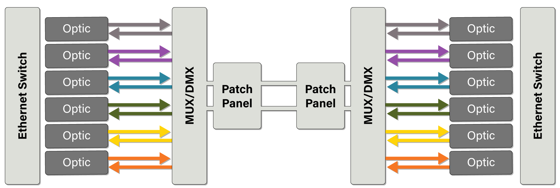
Given these values, we can use the optical reach and power budget – along with the logical diagram shown in Figure 2 – to determine how long of a cross-connect we can achieve.

If we assume the 40-channel filter has a high-performance loss of 3db each, the patch panels have a loss of 0.5db each and the fiber loss is 0.25db per km (ITU-T G.657.A1 and G.652.D or better), and we can work backwards to see what the total span distance is per optic/data rate.

Reviewing the numbers in Figure 3, we can see that once you go beyond the 10G data rate, the unmodified reach becomes the limiting factor. For this illustration, we can expect to be able to establish some versatile, yet high-capacity, cross-connects.
We had already reviewed the capacity of a passive 40-channel system using 10Gbps optics and know that it can support 400Ghz worth of capacity. Using the same methodology, we can create links with a total line capacity of 1Tbps @ 25Gbps per channel up to ~15km, 1.6Tbps @ 40Gbps per channel up to ~8.8km, and a 4Tbps total capacity up to ~1.5km in fiber length. Knowing this can help reduce the total number cross-connects needed between any two points.
Also, worth noting: Not all channels need to be the same data rate. If the link distance is designed to work with 100Gbps links (or approximately 1.7km), that same link will be able to support 10G, 25G and 40G channels as well.
Summary
Earlier we mentioned that we were “removing a lot of noise” - and then continued to make a great deal of assumptions to come up with these numbers. For instance, Forward Error Correction (FEC) is required and must be available on the host device for the links 25Gbps and higher. We made assumptions about fiber type, used calculated losses for the fiber spans, and assumed the total SFP+, SFP28, QSFP+, and QSFP28 ports were available at each end.
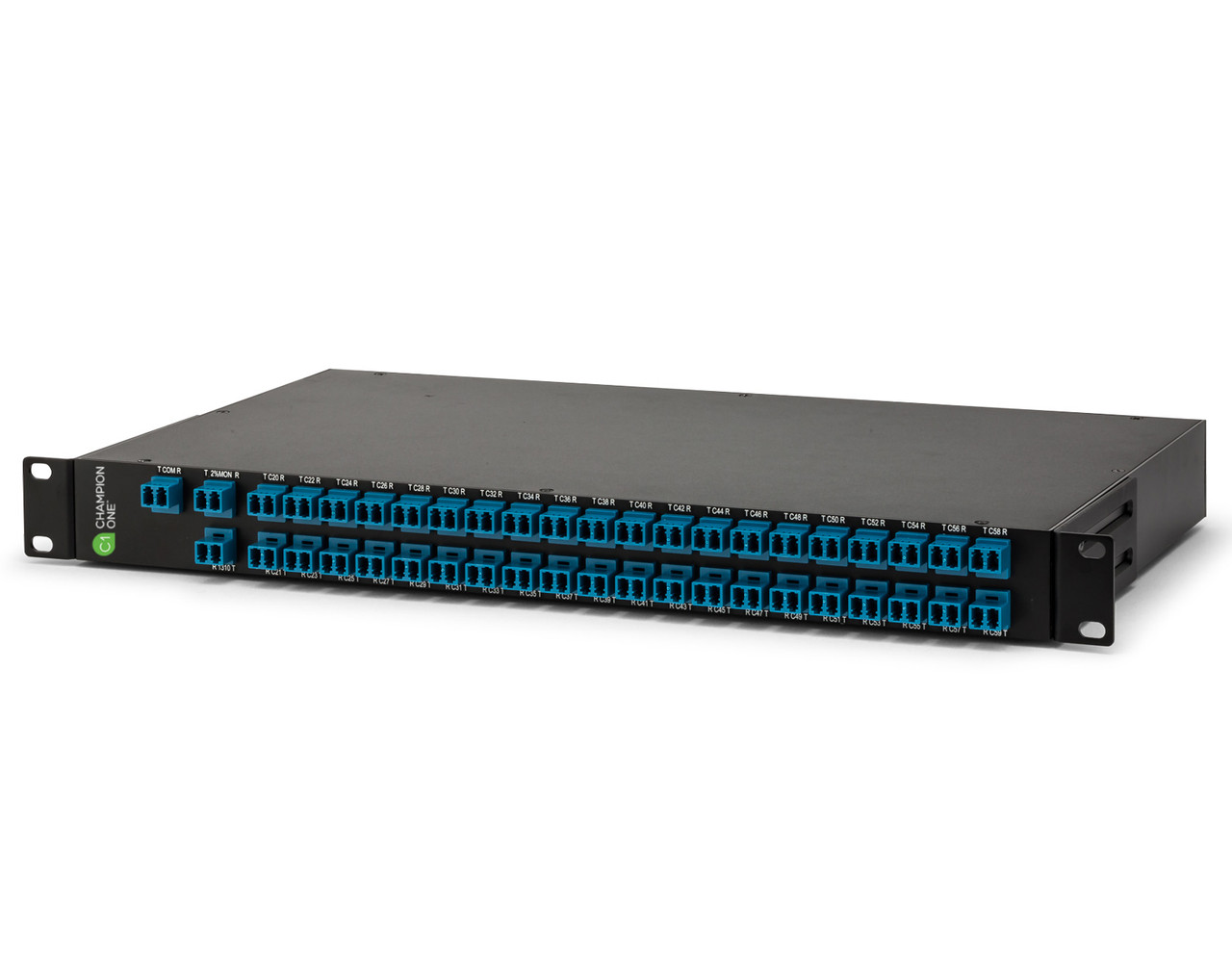
What this proved is that by combining passive filters and DWMD optics, we can increase the capacity as much as 40x per cross-connect pair. All this needs no power (except the switches), can be turned up very quickly, requires only 1RU of rack space (not counting the switches or patch panels), and adds zero latency.
As it should be clear by now, this is not meant to be taken as gospel, and every effort should be made to know the optic specifications you are considering, the fiber type of the cross-connect, and have measured fiber loss and dispersion values before deploying.


