Exploring DWDM Topology
Posted by Larry Legg on Jun 30, 2023

In our continuing exploration of Dense Wavelength Division Multiplexing (DWDM), topology is an important piece of the network that needs to be discussed. Fortunately, we’re not going to go deep into the mathematics of topology as that would probably end with a quiz, and I would like to limit that as much as possible. However, math is always a part of fiber optic networking, so there’s no way around that.
DWDM networks are a cost-effective solution for fast data transmission and higher capacity, but as always, we have to get that data from here to there. We need to do that effectively and efficiently.
I want to begin by saying that for the purposes of this article, we’ll be discussing Layer 1 fiber optic network topologies, not Layer 2 (MAC Address) or Layer 3 (IP Address) network topologies. Those are traffic patterns that are “layered” on top of Layer 1 (Physical) fiber optic network topologies.
DWDM Connections and Dynamics
Channels in DWDM are carried over a specified wavelength (optical channel) and different channels may carry different data (e.g., voice, data, video, data packets), and each at different bit rates. The transmitter-receiver optical link has several components, including fiber(s), optical Multiplexer and Demultiplexer filters, and possibly optical amplifiers.
Also important is if the client/customer owns their fiber, or leases. That determines whether you’re working with the end-user or a middleman. In this situation, either is fine — you just need to know who you’re talking to. Whether the customer leases or owns the fiber may also determine the topology you choose. It’s important to understand how it’s laid out in the ground to determine the solution.
The bottom line is that topology and the traffic patterns drive the WDM you need to use and choose. Let’s say you’re trying to go from Point A to Point B, but then they build a shopping center in-between that needs services. Your planned topology goes right out the window . . . Back to the drawing board!
Another big focus of fiber optic network topology is that since 9/11, disaster recovery and fiber-redundant paths for business continuity is a top priority. Hospitals, airports and airlines, emergency first-responders, etc., all need to be connected when bad things happen, so when one fiber network goes down, there’s another to back it up.
Point-to-Point Topology
A point-to-point topology is the simplest and most basic form of DWDM network. It consists of two end points that are connected by a single fiber cable using one or two fibers, with an optical multiplexer at one end and an optical demultiplexer at the other end. The multiplexer combines multiple wavelength channels into one fiber, while the demultiplexer separates them at the destination.

Point-to-Point
While point-to-point is simple on the surface, ultimately, it depends how the fiber cable is laid out to determine if it’s the right solution or if additional complexity is necessary.
A point-to-point topology can also include optical amplifiers along the fiber to boost the signal strength and extend the transmission distance. It’s also suitable for long-haul transport applications that require high speed, high bandwidth, high reliability, and fast restoration. However, it has some limitations, such as low scalability, and low flexibility.
Drop-and-Continue
Drop-and-Continue (a.k.a. Linear Chain or Passive Cascade) fiber optic network topology is a type of point-to-multipoint topology. With this, a single fiber optic cable is used to connect multiple endpoints in a network. The cable runs from a central location to multiple endpoints, and each endpoint has its own drop cable that connects it to the main cable.
Since drop and continue is a single linear direction, it can hold many channels on one end (say 40) and then split those up into 8 each, for example, in 5 different directions at the other end.
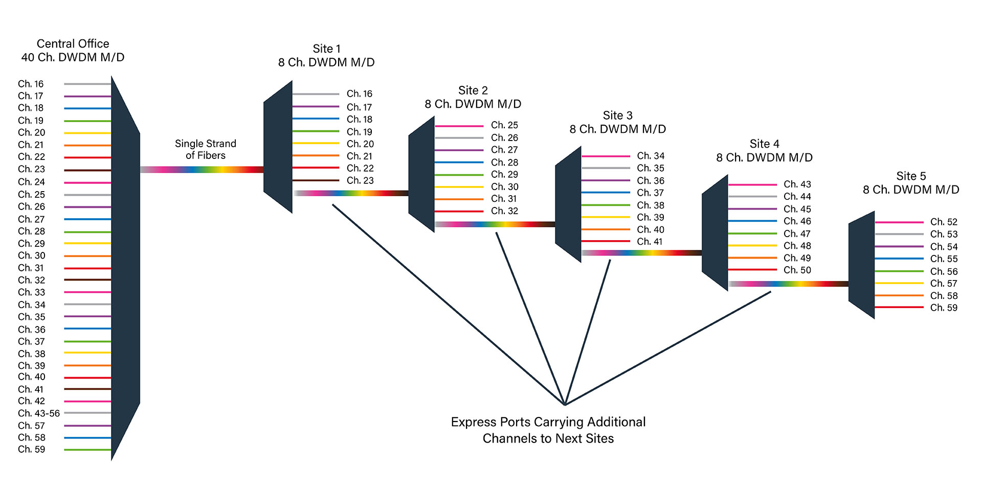
Drop-and-Continue
Ring and Arc Topology
Ring Topology means basically what it sounds like — the network is in a ring or arc connecting multiple nodes. It can run for kilometers through a local or metro area.
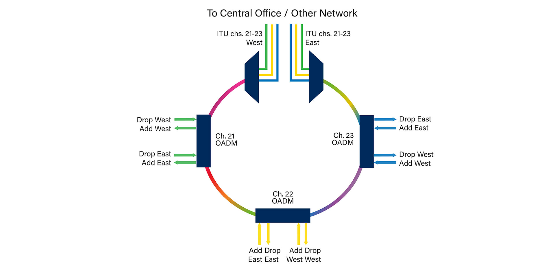
Ring and Arc Topology
One of the nodes on the ring is a hub station (a.k.a. “open node”) where all wavelengths are sourced, terminated, and managed — connectivity with other networks takes place at this hub station. Each node and the hub have OADM to drop off and add one or more designated wavelength channels.
In DWDM ring networks, the hub station may source and terminate several types of traffic, and it manages all channels (wavelengths) assigned to a path between nodes (and also the traffic type). At an OADM, optical frequencies are dropped off and added, whereas the remaining frequencies pass through transparently.
The main advantage of a Ring Topology is that it provides redundancy and fault tolerance. If one node or cable fails, the data can still travel around the ring in the opposite direction. A Ring Topology includes two fiber paths for network protection. In case of a fiber cut or a node failure, the traffic can be switched to the backup path in a short time.
A Ring Topology is suitable for local or metropolitan area applications that require high connectivity, high scalability, high flexibility, and high availability. However, a Ring Topology does have some drawbacks. It can be difficult to add or remove nodes from the ring without disrupting the network engineering. Also, there may be signal loss due to multiple OADMs, complex channel assignment and management, and potential congestion at the hub station.
Think of an Arc as a ring that has two hub locations — one on each end for redundancy. When a simple point-to-point has OADMs added, it becomes an “Arc”. This incorporates optical add-drop multiplexers (OADMs) at intermediate points to drop or add some wavelength channels without affecting the others.
Hub-and-Spoke
Hub and Spoke topology is designed for remote distribution without the need for a PoP (Point of Presence) with powered transport gear. The main Multiplexer (Mux) / Demultiplexer (Demux) is often a 40-channel unit that goes to a bandpass Mux/Demux in a pedestal or splice enclosure. From the Band Pass, it splits into 5 fiber cables that have 8 channels each to remote endpoints.
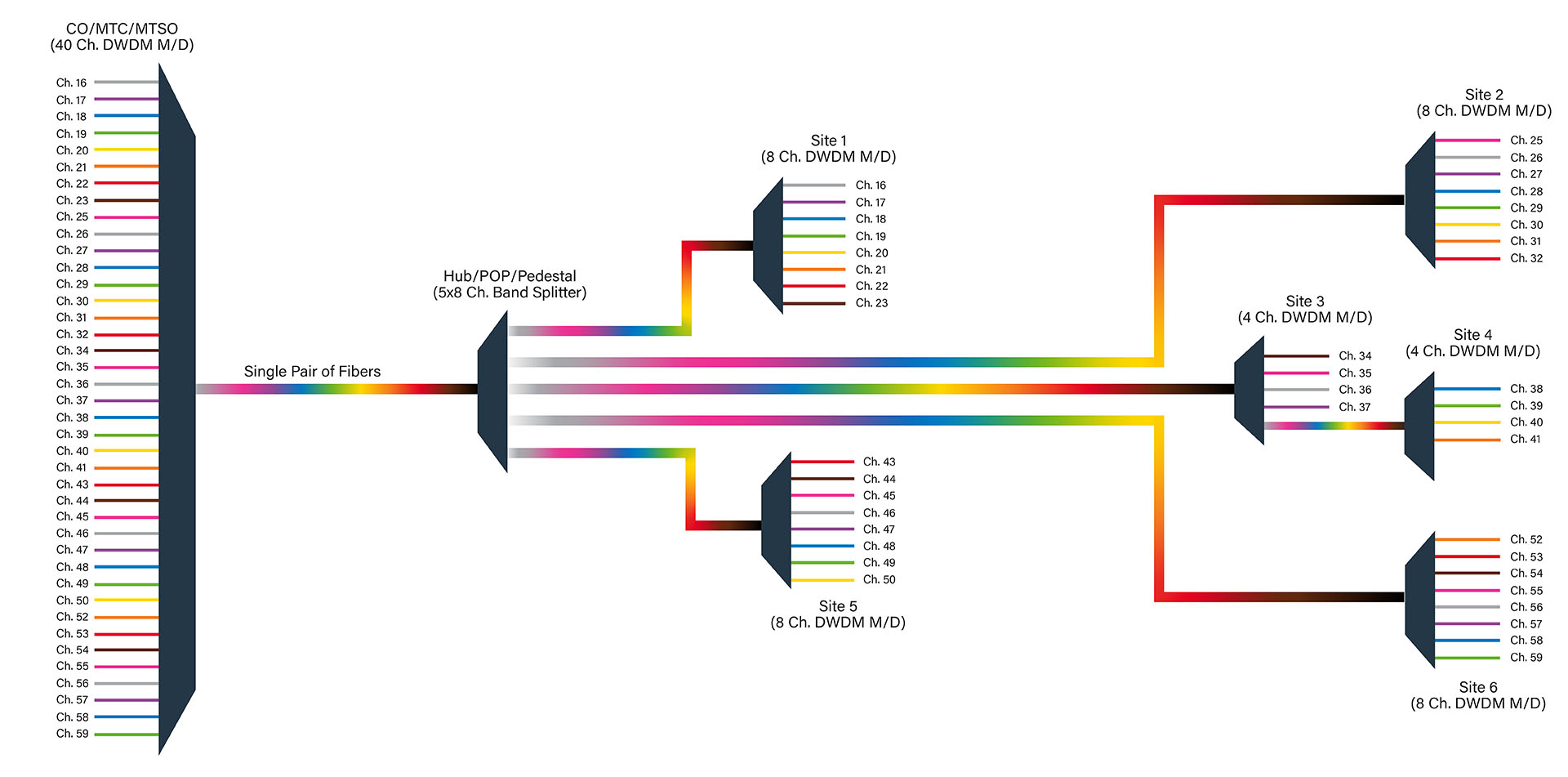
Hub-and-Spoke
The main advantage of a Hub-and-Spoke Topology is that it is easy to install, manage, and troubleshoot. If one endpoint fails or disconnects, it does not affect the rest of the network. The central device can also monitor and regulate the traffic on the network.
However, there are some downsides to Hub-and-Spoke: It depends on the central device for its functionality, which creates a single point of failure. Although it is a completely passive device and is not prone to failure, if the central device malfunctions, the entire network goes down.
Conclusion
Fiber network topology is essential in not just connecting it all together, but how to connect it so each point in the chain works, and works well. Planning and understanding the options and alternatives are crucial to a successful DWDM topology implementation.
The requirements and needs of each DWDM fiber optic network topology differ and involve various optical components to get it right. There are the common DWDM topologies, and they get more complex as the client needs become more intricate. You’ll need to prepare the most efficient set-up so you (hopefully) don’t have to go back and change it out later.
If you have questions and need to explore the equipment choices for your fiber optic networking project, feel free to contact Approved Networks for information.
Related Products
 40 Channel, DWDM, Band Pass Splitter, 8 Skip 1, Ch. 16 start, 5 Band, LGX box, LC/UPC
 40 Channel, DWDM, Band Pass Splitter, 8 Skip 1, Ch. 16 start, OSP Cassette, 1meter, 900um, LC/UPC
 40 Channel / 20 Service DWDM, Single Fiber Mux, Ch. 21-60, 1RU, Rackmount