What is Power and Why Does it Matter in Optical Circuits?
Posted by Tim Yanda on Mar 10, 2023

Have you considered the question: “How much power does an optical transceiver have?” Or: “How much power does a transceiver require?”
It is important to differentiate the terms “have” and “require”. More importantly, we look for the meaning of “power” as several dictionaries have upwards of thirty definitions of the word. Some are obviously not applicable in our case, but a few are: “To supply with electricity or other means of power; conducting electricity; energy, force, or momentum.”
What do any of these have to do with optical transceivers?
Amps, Watts and Volts
We all know transceivers require electrical power to operate. Commonly this specification is expressed in terms of Watts. Formally, it is expressed as: Watts = Volts x Amps, or W = V x A.
Why is this important? If we know how many watts are required, we can determine how much power is required at each transceiver port in the switch to ensure the transceiver functions properly. This is generally not an issue with SFP and SFP+ transceivers as most switches supply more than adequate electrical power for them to function properly.
Where this can be an issue is with longer reach QSFP28, QSFP-DD and OSFP parts.
Switch ports are rated by power class, and each power class is based upon the Multi-Source Agreement (MSA) for the respective form factor. The takeaway is to ensure you know what the switch port electrical power capabilities (i.e., power class) are when planning your network. This is one type of power that gets discussed when dealing with transceivers.
Optical Power, dB and dBm
“Optical Power” is the other common question that arises. Optical Power is expressed in “dBm” (decibel milliwatt) — not to be confused with “dB”. The unit “dB” expresses the difference between two “dBm” values or the loss of a span of optical fiber. A measurement of 0 dBm using an Optical Power meter indicates 1 milliwatt of power.
It is important to understand the difference between “dB” and “dBm” in fiber optic measurements when working on optical communication systems. Optical Power and Optical Power Loss are common in all optically energized systems.
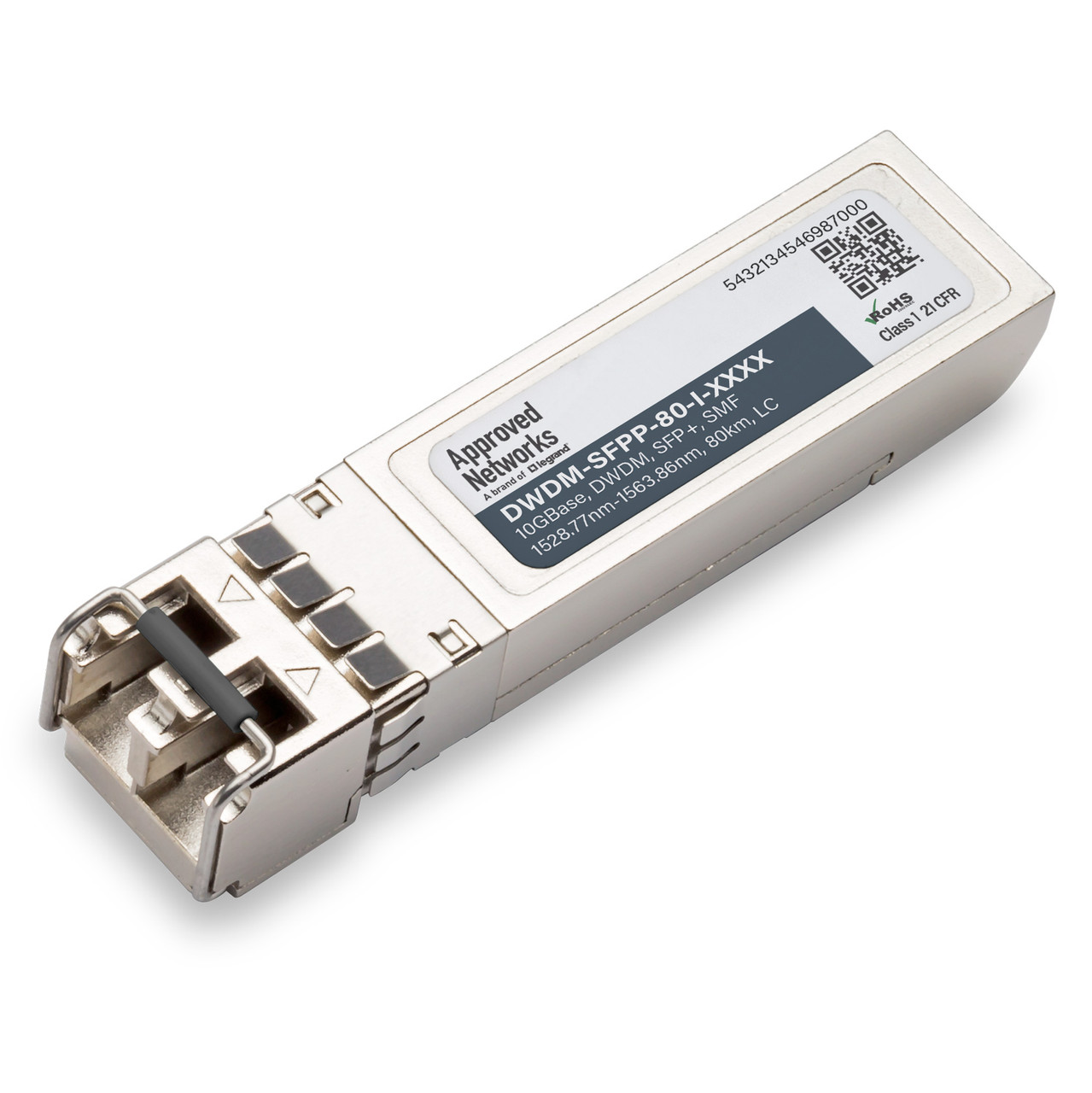
Let’s take a look at an SFP+ transceiver. First, we need to know what the actual part is:
Once we know the part, we can look up what the transmit or Tx power is both in minimum and maximum “dBm”. Then we need to look at the receiver sensitivity or minimum receive power, then the maximum or overload specification. By knowing all these numbers, we can determine what the link budget is in “dB”.
Both “dB” and “dBm” are in logarithmic scales and are non-linear measurement units. When the optical power level is halved or doubled, there is a 3 dB decrease or increase in the optical strength. A note of caution: If the maximum power output is greater than the maximum receiver specification (“overload power”), you cannot conduct loop-back testing without attenuating the signal as you will damage the receiver.
OTDR, Link Budgets and Link Losses
The last part of planning a circuit is how long is the fiber span from the beginning to the end. It is best to OTDR (Optical Time Domain Reflectometer) the circuit to confirm the loss of the fiber. In the absence of an OTDR measurement, you can estimate the loss based on the typical loss of fiber. The following is what is standard, at 1310 nm loss is ~0.35 dB/km and 1550 nm loos is ~.25 dB/km. All of these specifications are important to understand when planning a circuit.
Once we know the link budget (transceiver) and the link loss (fiber), we can select the correct transceiver. For example, if the link loss is 10 dB, then the correct part would be 10G SFP+ ER as it has the capability to support up to 16 dB worth of link loss. As such, the part has sufficient optical power to overcome the 10 dB link loss at 1310 nm and still have good margin for unaccounted for fiber losses.
As you can tell, Optical Power is different than Electrical Power, and each are needed specifications when successfully planning a fiber optic network link. Once you know the link budget and the link loss, you can successfully plan the circuit.
In this example, while we used 10G SFP+ parts, the basic concepts hold true for 1G and up parts. The key specifications are link budget, link loss, and power draw in amps, and by knowing these key specifications, you will be able to plan a successful circuit.
The team at Approved Networks will be happy to discuss your questions on circuit strategy to assist you in successfully planning and implementing your installation.
Related Products


